Construction
Motor Module
Printing
The motor module files are available in on-shape: Motor Module
Open the document and print the following:
- 1 Motor Module
- 2 axis stoppers
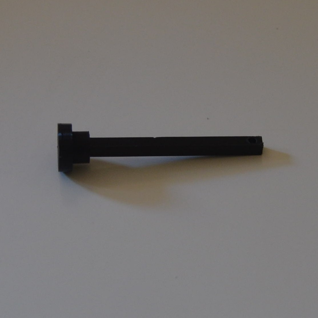
- 1 axis
- 1 axis gear
- 1 motor gear
- 1 motor shaft adapter
Most parts are parametrized by variables. Two important ones to tune the printing process are:
- sliding_clearance: the clearance needed for two parts in contact to be able to slide
- no_slide_clearance: the clearance needed for one part to fit into another, but not slide.
- base_shrink: holes shrink more at te bed than at the other end, this term accounts for that
Additional Parts & Tools
Aditionally, you will need:
- 6 Polulo screws #2-56 1/4”
- 1 Polulo screw #2-56 3/8”
- 6 Polulo machine hex nuts #2-56
- A Polulo micro metal gearmotor . I used a HPCB 12V one, I think any of those, but the 1:1000 gear ratio will do.
- A Polulo motor bracket
- An assebled holonomic wheel (instructable in progress)
- A controller circuit (optional)
- A hammer
- A small phillips screw driver
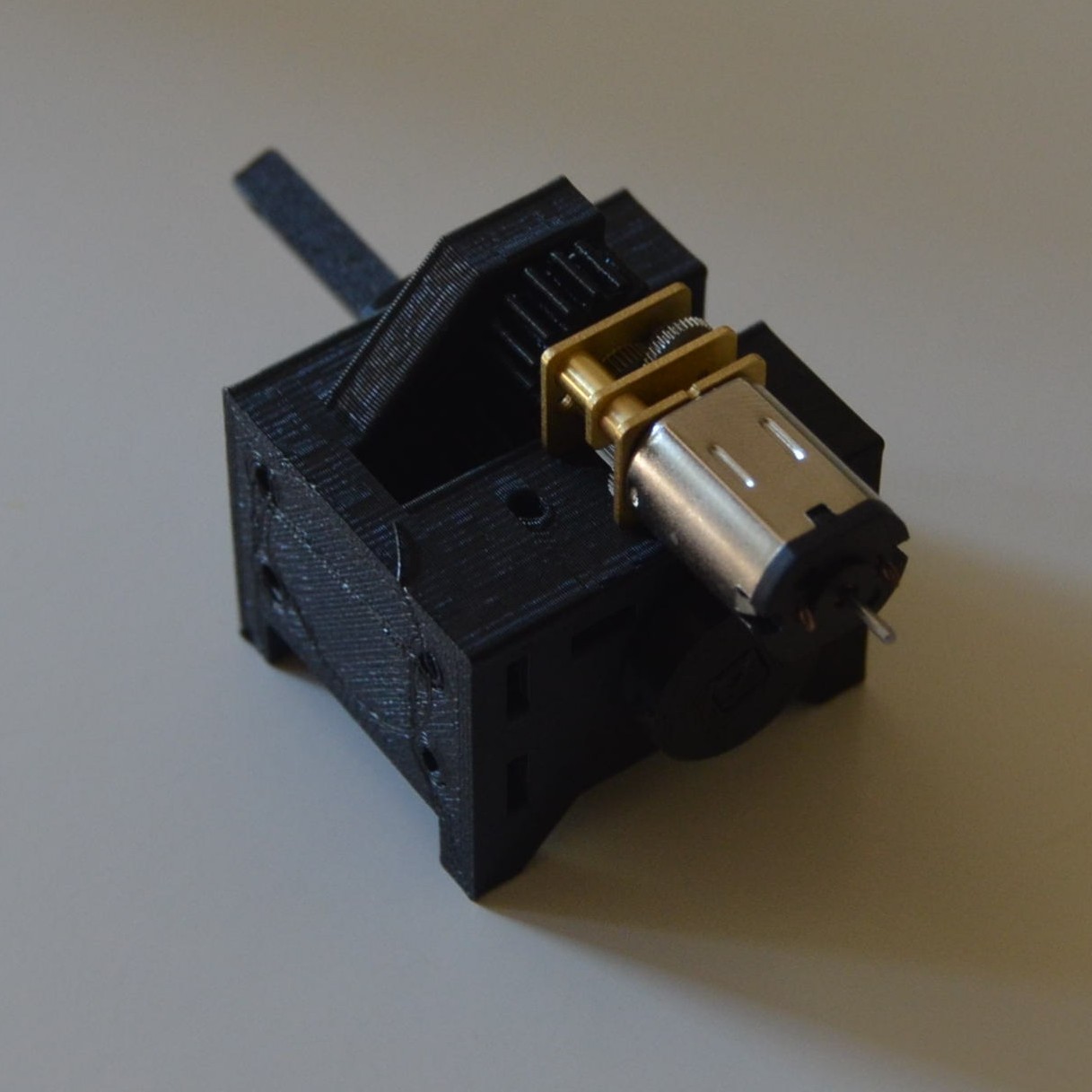
Assembly
You may have to use a hammer throughout this process, as the pieces are preassure fitted.
After making sure the assembly is correct, you might want to use super glue (or “la gotita”) to fix some of the parts, so you don’t depend on pressure for things to stay together.
-
Insert one axis stopper into the axis.
-
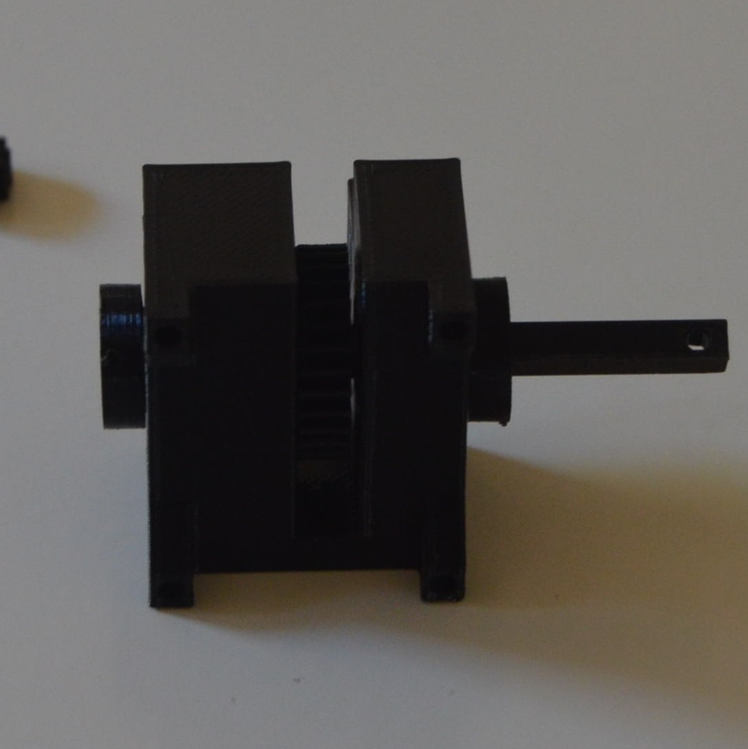
Insert that assembly trhough the middle whole of the module, and through the bigger gear.
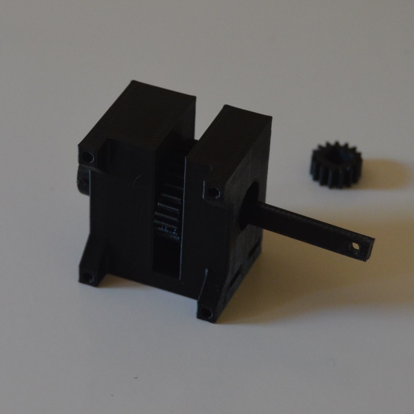
-
Put the other stopper at the other end of the axis. Hammer until it pressess the module’s wall. Then open the walls with your finger to push the stoppers away, until you cannot feel the friction between the stoppers and the module anymore.
-
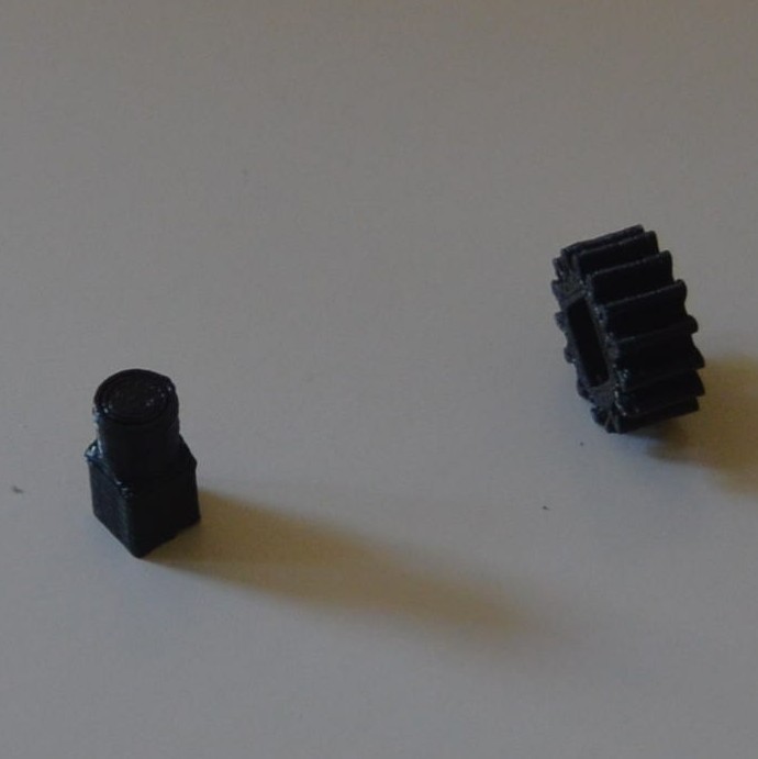
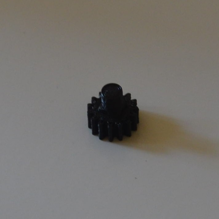
Insert the smaller gear into the motor shaft adapter.
-
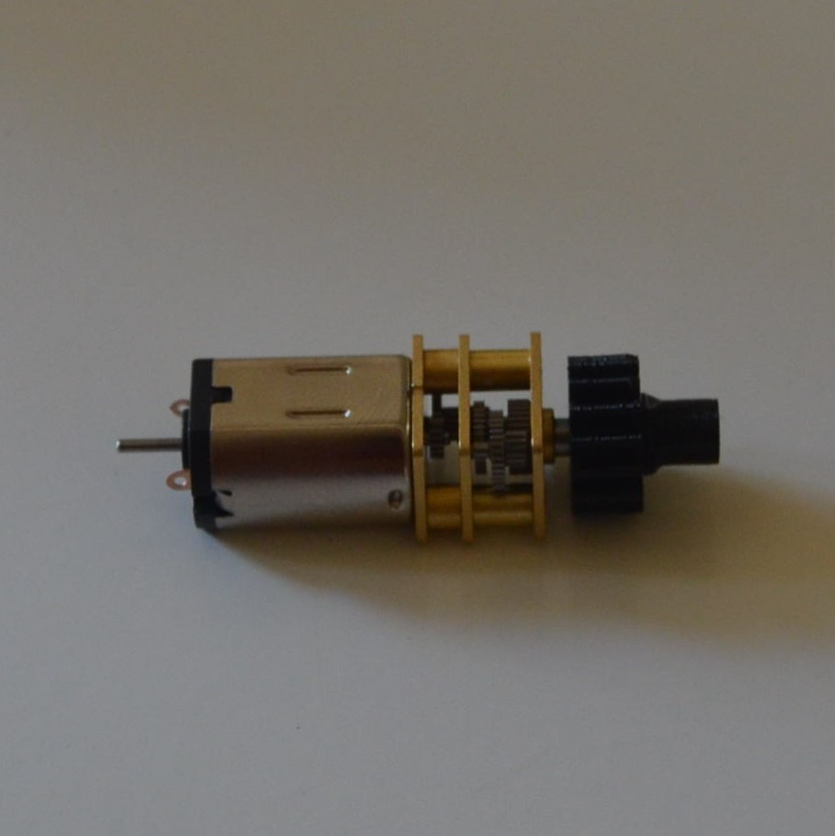
Insert the assembly into the motor. You may have to use a hammer here too, be gentle. A hollow tube might prevent you from having to hammer the axis extension of the motor (I tap it gently and hasn’t been deformed).
-
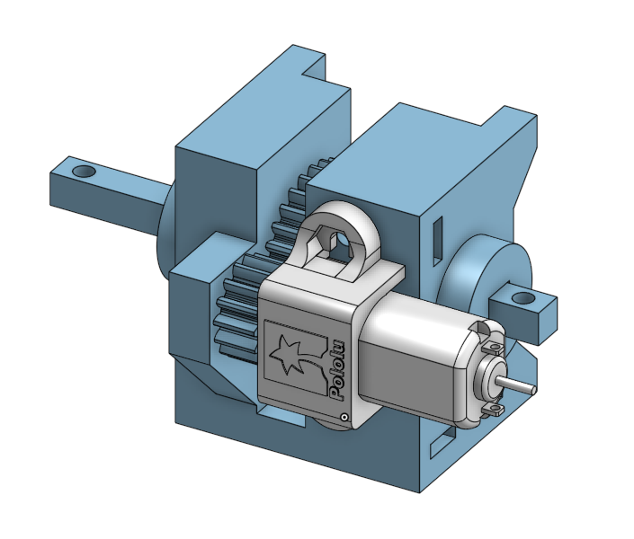
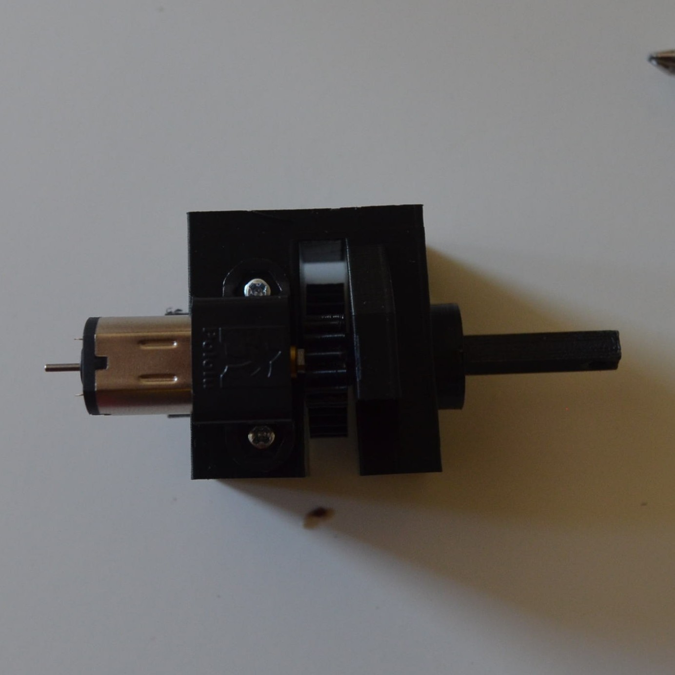
Place the motor besides the gear. Ensure the shaft adapter fits loosly in the holder.
-
Place the motor bracket around the motor. Place nuts on the prisoner holes. Fit the screws.
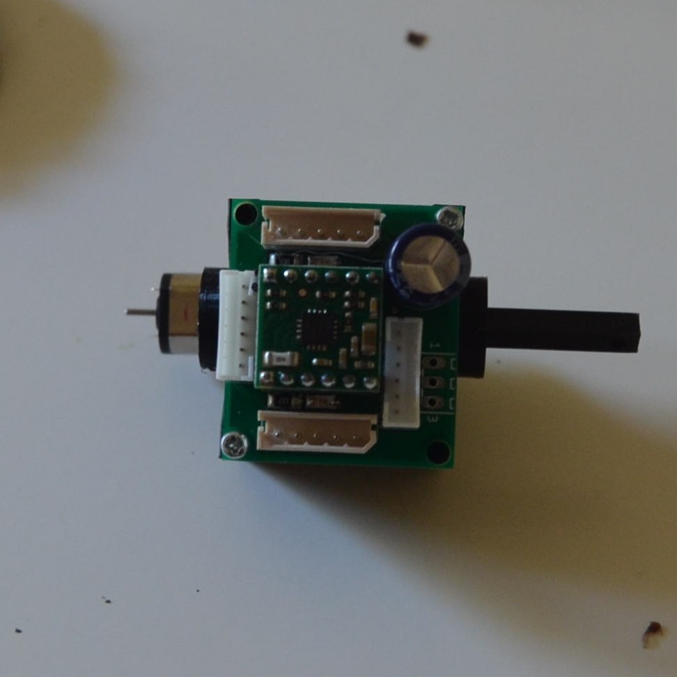
-
Mount the control circuit
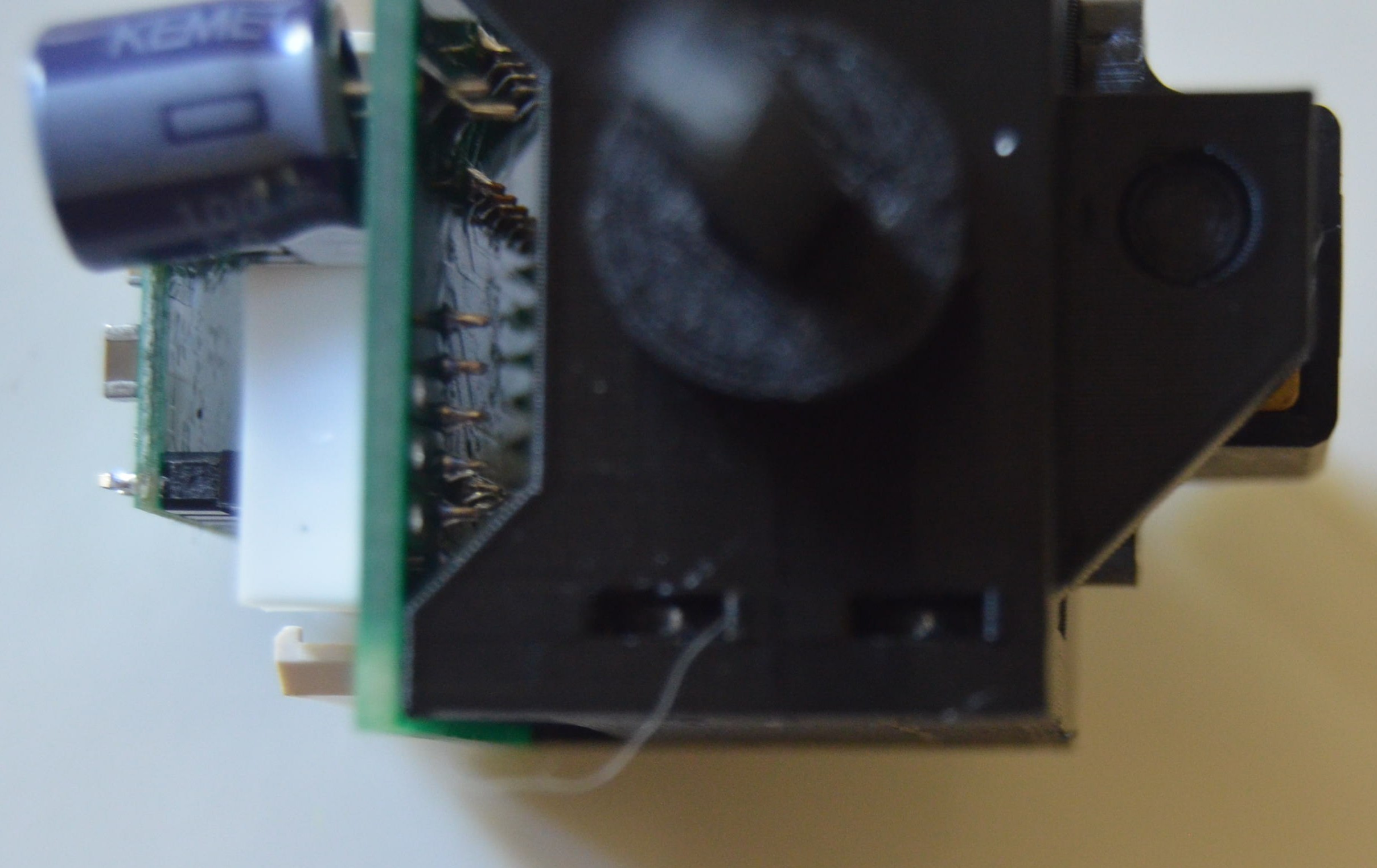
-
Place the prisoner nuts on the prisoner holes for the module mountings on the bottom, both sides.
-
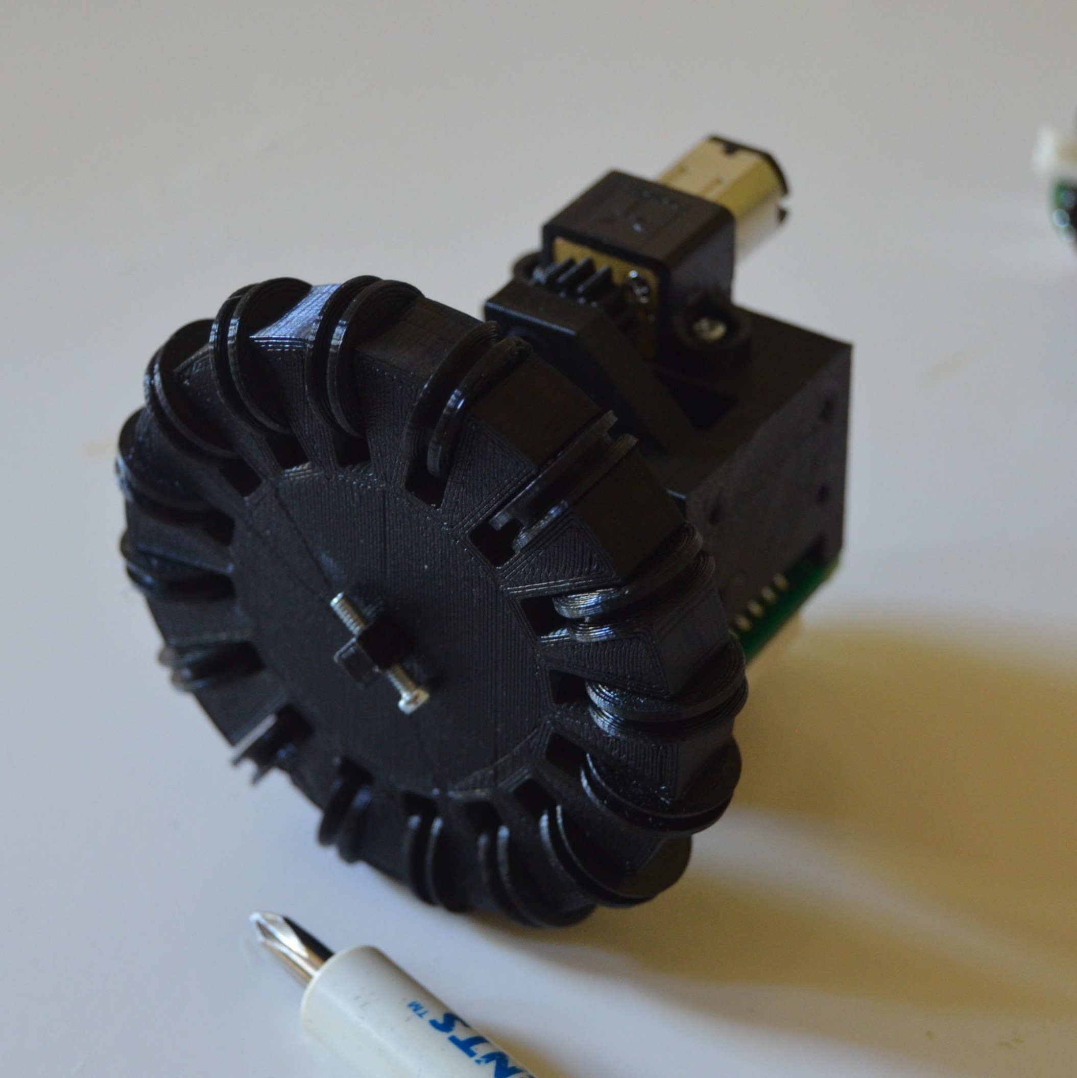
Fit the wheel through the axis. Place a 3/8” screw to keep it from falling off.